Understanding Hourglassing and Artificial Energy in Abaqus
This blog post explores the behavior of reduced-integration solid elements (C3D8R) in Abaqus, with a focus on hourglass section control, artificial energy, and the effect of mesh refinement and hourglass stiffness scaling. Mainly it's an investigation into the industry standard or Abaqus guideline that the artificial energy (ALLAE) introduced by these mechanisms should ideally remain below 5–10% of the total strain energy (ALLIE)
For reference or repeat studies: all the following is performed on a 10×10×100 mm clamped beam (E = 200,000 MPa, load = 1000 N), using Abaqus standard 2025.HF4, NLGEOM = OFF. In an easy hand calculation, this gives a 2mm displacement and 600MPa maximum bending stress.
1. Introduction
Hourglassing is a numerical artifact in reduced-integration elements where deformation occurs without corresponding strain energy. See e.g. some other interesting blog posts fidelisfea and systemworkx.de where also the Euler formula is given for the hand calculation.
Abaqus counteracts this with hourglass stiffness (default in Abaqus standard) or enhanced control (default in explicit but also possible in Standard) .
2. Element Types and Controls
Element Type | Description |
C3D8I | Fully integrated, robust for bending, no hourglassing but higher cost. 8 integration points |
C3D8R - default | Reduced integration, 1 integration point. Default stiffness hourglass control |
C3D8R - Stiffness 0.1 | Reduced integration, 1 integration point. Stiffness hourglass control scaled factor 0.1 |
C3D8R - Stiffness 10 | Reduced integration, 1 integration point. Stiffness hourglass control scaled factor 10 |
C3D8R - Enhanced | Reduced integration, 1 integration point. 'Enhanced' hourglass control |
For the C3D8I I didn't go finer than 4x4: this is the most 'honest' comparison with 8x8 C3D8R elements in terms of runtime as the amount of integration points will be the same.
3. Results
3.1 Displacement Results (mm)
Mesh | C3D8I | C3D8R-Enhanced | C3D8R-Stiffness (default) | C3D8R-Stiffness (0.1 scale) | C3D8R-Stiffness (10 scale) |
2x2 | 2.0125 | 2.013 | 2.67 | 2.68 | 2.58 |
4x4
| 2.015 | 2.015 | 2.15 | 2.15 | 2.13 |
8x8 | - | 2.017 | 2.05 | 2.05 | 2.04 |
Key Observations:
- C3D8I and C3D8R-Enhanced are the closest. They produce an accurate displacement of ~2.015 mm right away, even on the extremely coarse 2x2 mesh. Their results are stable and consistent as the mesh is refined.
- C3D8R with stiffness control behaves badly. On the 2x2 mesh, all variants are over 25% softer vs the theoretical result. Results only begin to approach the correct answer with a much finer mesh (8x8). Bit surprising that even a factor 10 stiffness didn't do much.

(C3D8I and the Enhanced C3D8R are overlapping on the plot, I'm too lazy to make a new one where that's clear)
If you send me a message with the correct reason why we are converging on 2.015 and not 2 mm, the next beer is on me if we meet ;)
3.2 Energy Results
3.2.1 Artificial Energy Table
Mesh | C3D8R-Enhanced | C3D8R-Stiffness (default) | C3D8R-Stiffness (0.1 scale) | C3D8R-Stiffness (10 scale) |
2x2 |
250.6 |
7.40 |
18.43 |
49.25 |
4x4
|
63.08 |
1.55 |
0.75 |
8.72 |
8x8 |
16.05 |
0.65 |
0.78 |
2.26 |
3.2.1 Strain Energy Table
Mesh | C3D8I | C3D8R-Enhanced | C3D8R-Stiffness (default) | C3D8R-Stiffness (0.1 scale) | C3D8R-Stiffness (10 scale) |
2x2 | 1006.83 | 1006.98 |
1339.09 | 1360.55 | 1291.10 |
4x4
| 1008.37 | 945.32 |
1074.96 | 1078.23 | 1059.02 |
8x8 | 993.18 | 1025.99 | 1027.50 | 1021.78 |
3.2.3 AE / SE ratio
I know nobody looked at the tables above, so here is the plot of the ratio! (for C3D8I AE = 0 so the ratio is also 0)
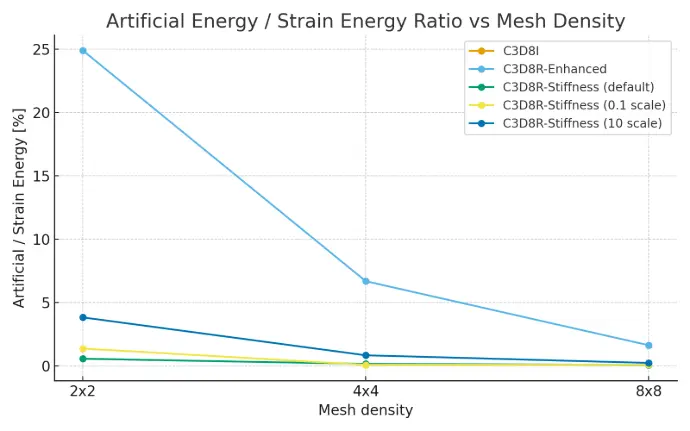
Now it gets interesting!
- AE goes down when the mesh is refined. This is what we expect so at least we have that.
- C3D8R-Enhanced shows high artificial energy on coarse meshes. For the 2x2 mesh, the artificial energy (250.58) is about 25% of the strain energy! This value drops significantly as the mesh is refined. The enhanced hourglass control does give good results in displacement and stress. Most likely it was developed exactly for this use case (simple bending?). However I'd be wary seeing this high AE with any other loading or geometry.
- Stiffness control has (much) lower artificial energy. While the stiffness-based methods show lower ALLAE, remember that the overall results (displacement and stress) were poor for the coarse meshes due to locking. This demonstrates that a low artificial energy value doesn't automatically mean the results are correct.
- For a 2x2 mesh, both the 0.1 and 10 factor stiffness have higher AE vs the default value. While the stiffness is lower, probably the 'work done' or displacements because of hourglassing are more? The 2x2 mesh with 0.1 scaling is also the only case with very visible hourglassing:
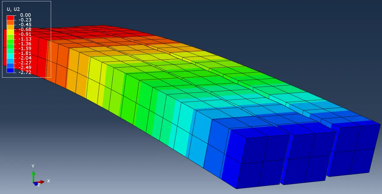
Displacement result (5x deformation scale factor) for C3D8R with default settings (left), 0.1 stiffness scaling factor (middle) and 10 scaling factor (right).
Conclusion: Do check your artificial energy. While the enhanced hourglass control in C3D8R-Enhanced is effective, it can be very aggressive on coarse meshes. This is a sign that mesh refinement is necessary for full confidence in (more complex) results. On the other end of the spectrum, low Artificial Energy is not a get out of jail free card! The above results clearly demonstrate this.
3.3 Stress Results
3.3.2 Stress at Integration Point (MPa)
The only results that makes sense with C3D8R elements with these coarse meshes are integration point values. (Maybe a future blog post on the interpolation of results to nodes and their visualization is not a bad idea).
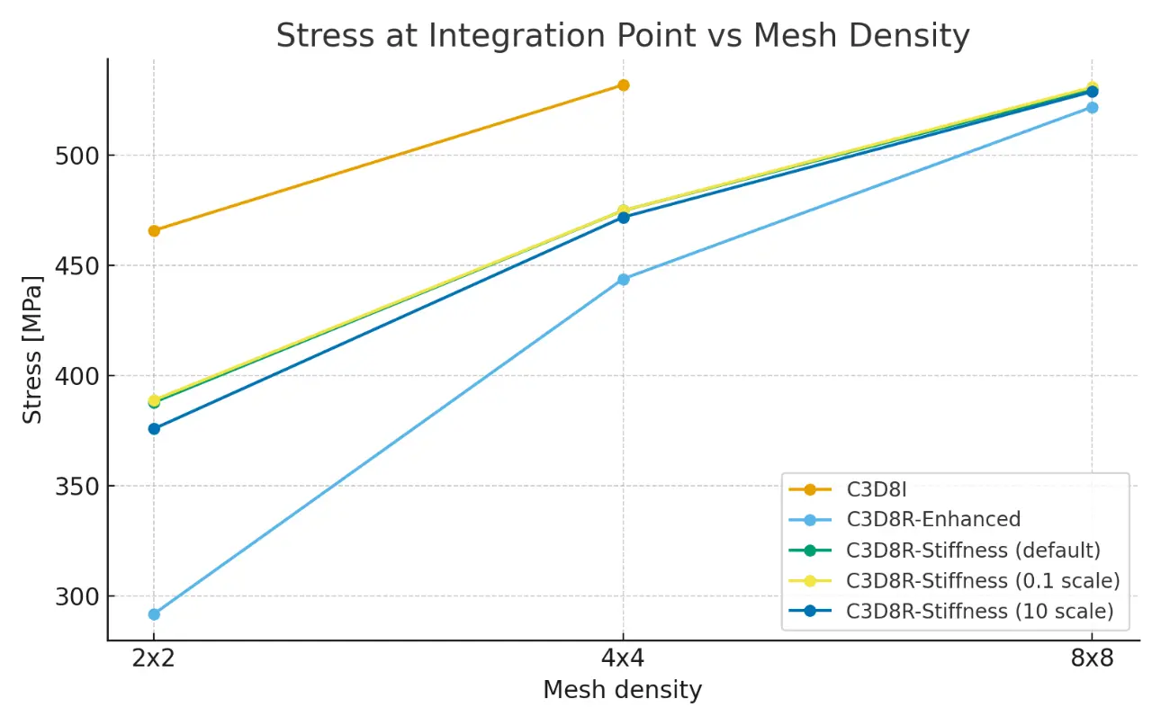
With these coarse meshes, the integration points are still far away from the surface, so we should check them vs the hand calculation at their actual location, or interpolate them to the surface. I choose the second option (next image)
3.3.3 Interpolated Stress to Surface (MPa)
In this simple case we can easily interpolate the known integration point location (halfway for C3D8R, at 1/sqrt(3) for C3D8I) to the place of maximum stress.
The theoretical result is 600 MPa.
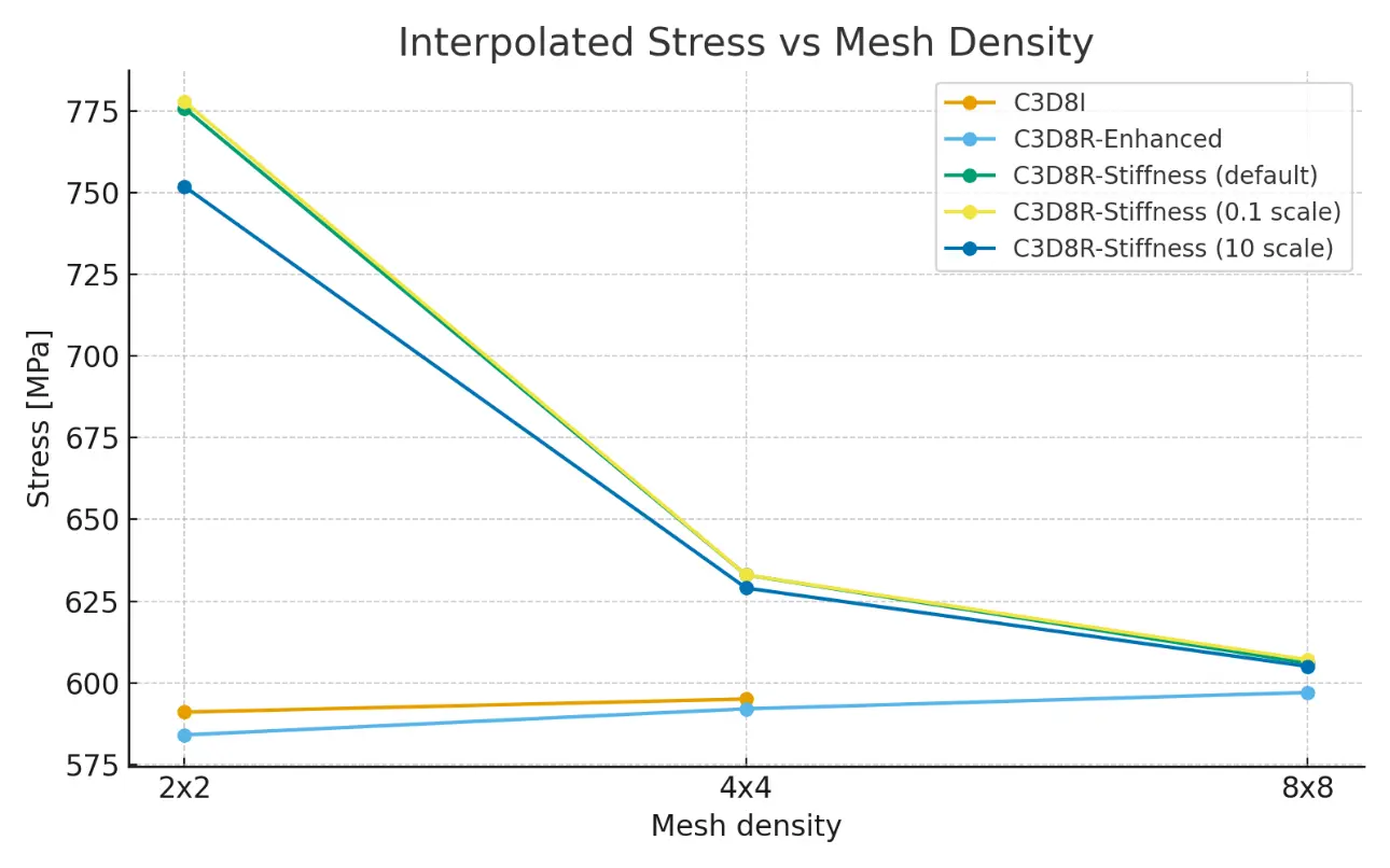
4. Discussion and conclusions
This blog is not about mesh sensitivity, but it serves as a reminder to definitely run a mesh sensitivity study if you care about the results.
It also (quite obviously) shows that for bending, the C3D8I elements are superior to the reduced integration linear ones.
Artificial energy acts as an indicator of numerical damping; high values signal poor element performance or insufficient mesh resolution. But mostly when you stay within a certain type of hourglass control. To me it was a bit surprising that the enhanced control also gave very good results at very coarse meshes, with (very) high AE! As mentioned before, it's possible that it is designed especially for this use case. With more time, I might look at the actual formula's and paper cited (however on a first search it seems to be behind a paywall ...).
Enhanced control seems to be introducing excessive artificial energy, particularly in bending-dominated coarse meshes, but with good reason, as with the default the response is not stiff enough.
Stiffness control with (large?) scale factor of a factor 100 has almost no influence on the results,.
And maybe the most striking result: with the default setting, we get
- no visible hourglassing modes
- ratio of AE over IE below 5% (even below 2% for 4x4 mesh)
But results that are still quite off!
Recommendations?
If you want recommendations from a random dude online:
- Wear sunscreen
- Do check the artificial energy and ratio with internal energy
- But don't use it as a justification on why your particular mesh or element type is bad or good!
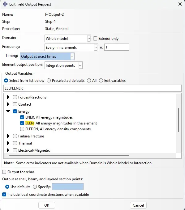
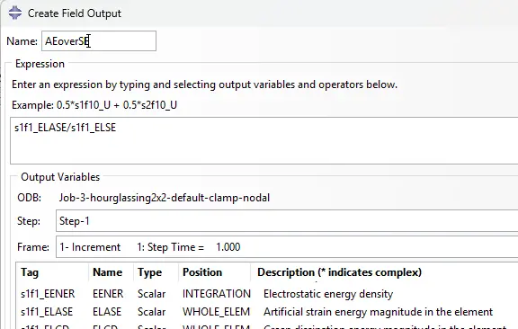
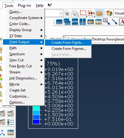
Also, don't forget it's possible to get Field output for energies, and using create field output you can plot the ratio too:
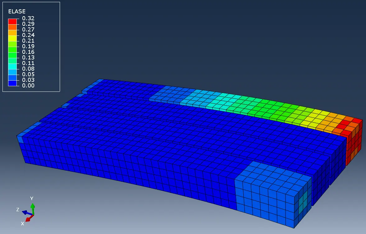
Artificial energy (ELASE - element artificial strain energy) for C3D8R factor 10 stiffness control (left), factor 0.1 stiffness, default, and C3D8R Enhanced control (right)
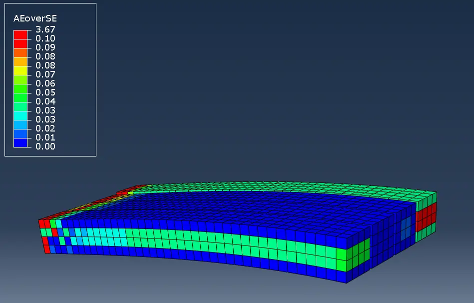
Artificial energy over Strain Energy for C3D8R factor 10 stiffness control (left), factor 0.1 stiffness, default, and C3D8R Enhanced control (right)
Do note that the highest ratios occur not in the locations with highest artifical energy, but mostly in the elements with almost zero strain energy.
Some info on how to get the above output: